This document explains how to send images taken by drone and make photogrammetric processing in Linaster cloud platform.
¶ Raw data Preparation
¶ Raw data from SD to computer
- Remove SD card from the drone slot, use a USB3.0 adapter and connect it on computer.
- On computer navigate to folder DCIM/Survey.
- Copy all images and files in a new folder on your computer (all images/files need to be on same root folder).
- Grab the target file from GNSS survey. Need to be ASCII and formated like:
- "Name, X, Y, Z" (Comma, Space, TAB or semi-column delimited).
- Syn file from Walker.
¶ Raw data to Linaster cloud
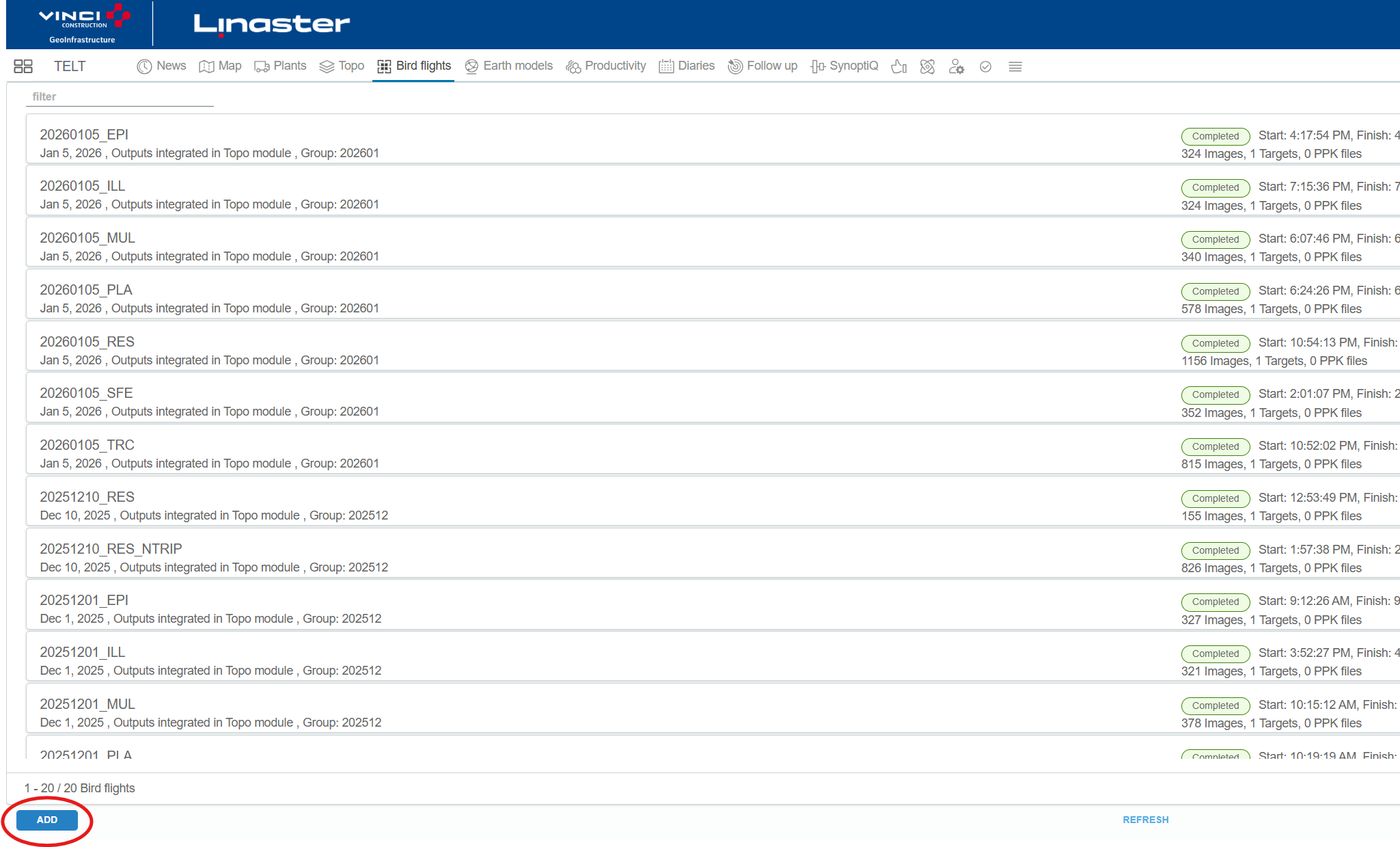
Go to https://linaster.online, enter your credentials, click on your project and on “Bird flights” tab.
Click on « Add » button to create a new flight processing.
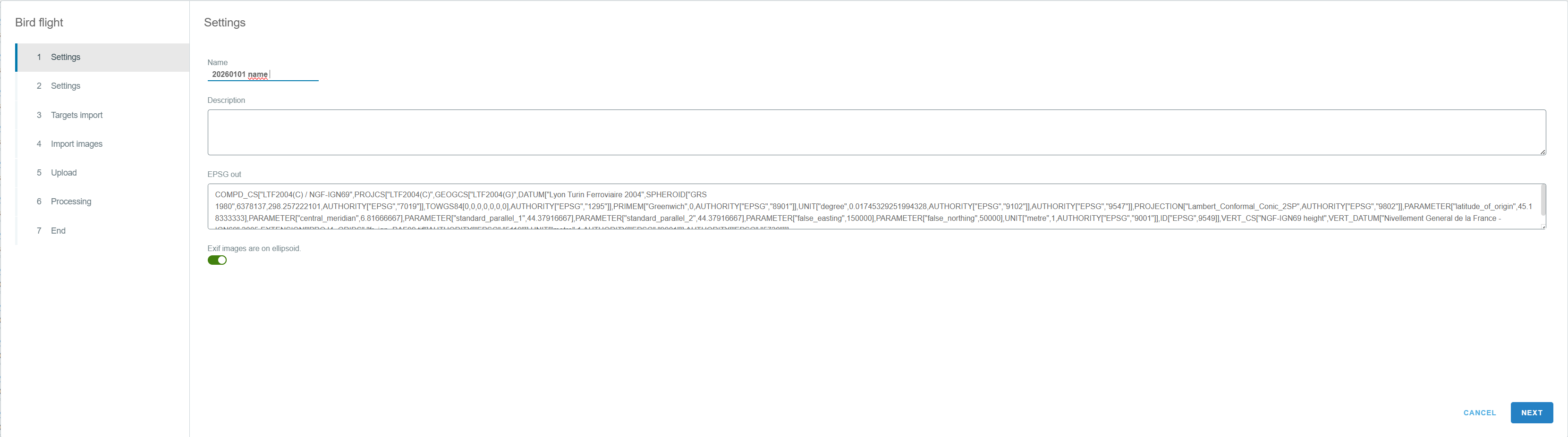
Enter the flight name, description if needed (do not change the EPSG code.). Tick the 'Exif images are on ellipsoid' if you have previously remove geoid from https://app.linaster.online or flew by NRTK/NTRIP.
Once it’s done click “next”.
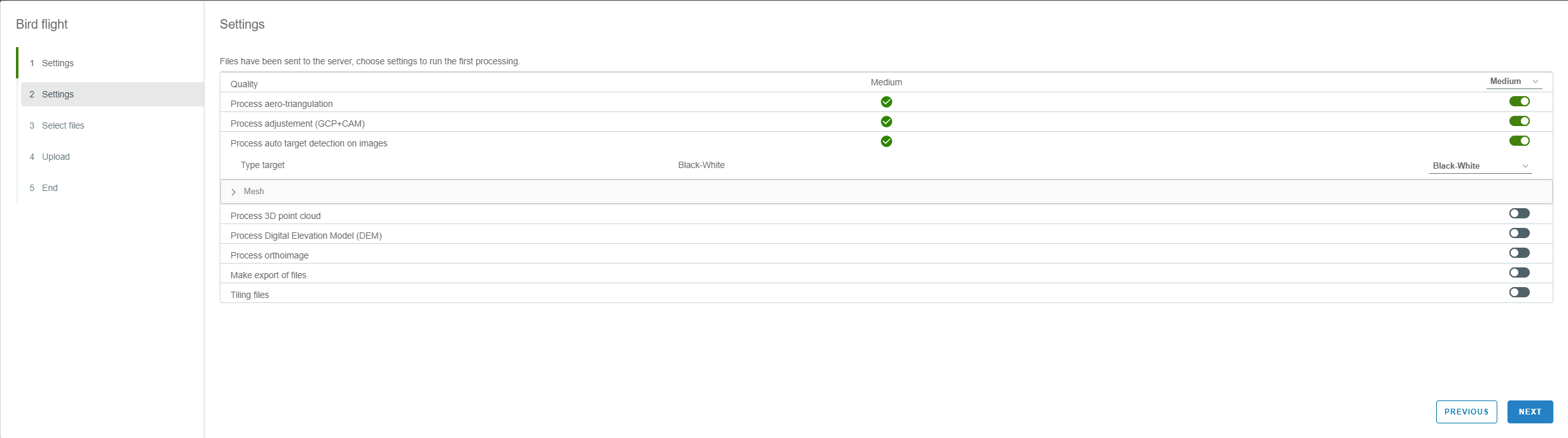
In step 2, only tick the "Georeferencing" button. Press “Next”.
On step 3, click on button "browse" to select the target file. Ajust the right parsing file parameters, and select the name X, Y, Z column in file.
If the file is well parsed you can see the points on map. If something is wrong the map is not showed.
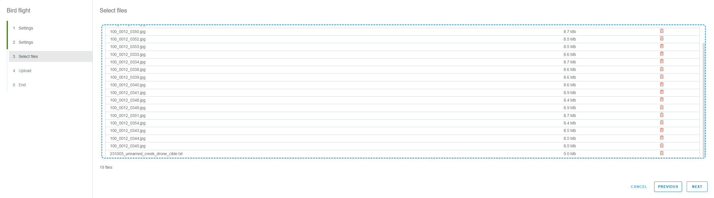
On folder containing all raw data, select all and drag and drop to Linaster box. Once you have controlled number of files between folder and Linaster, click next.
Eg: on windows: CTRL+A to select all file in a folder
At this step all raw data will be send to Linaster servers.
Don’t close the page or turn off the computer, otherwise the download will be cancelled.
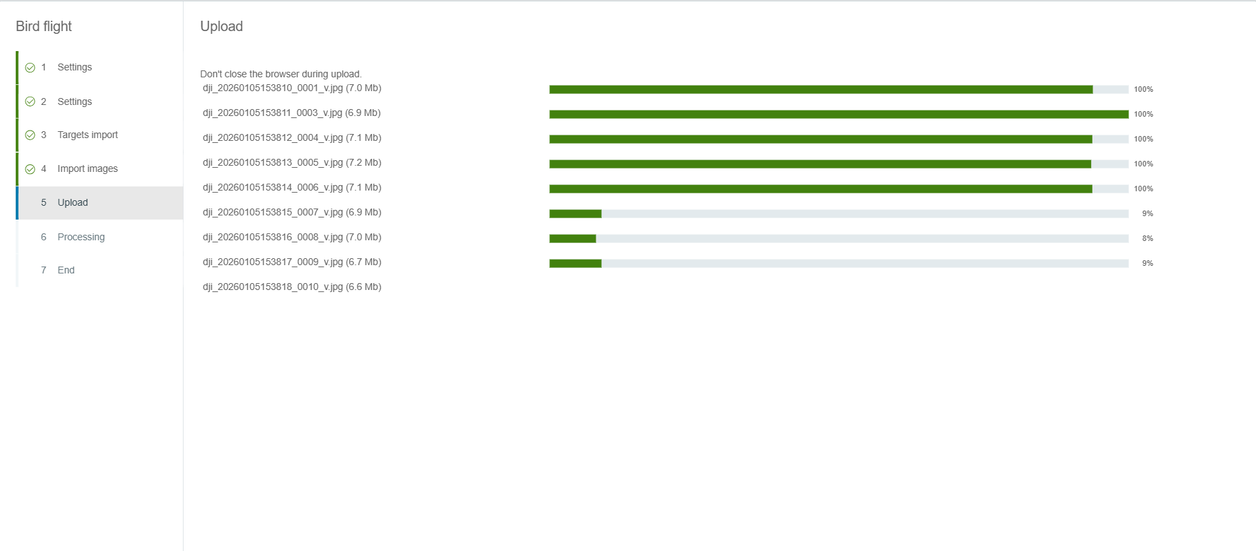
When the data download is completed, small steps is showed.
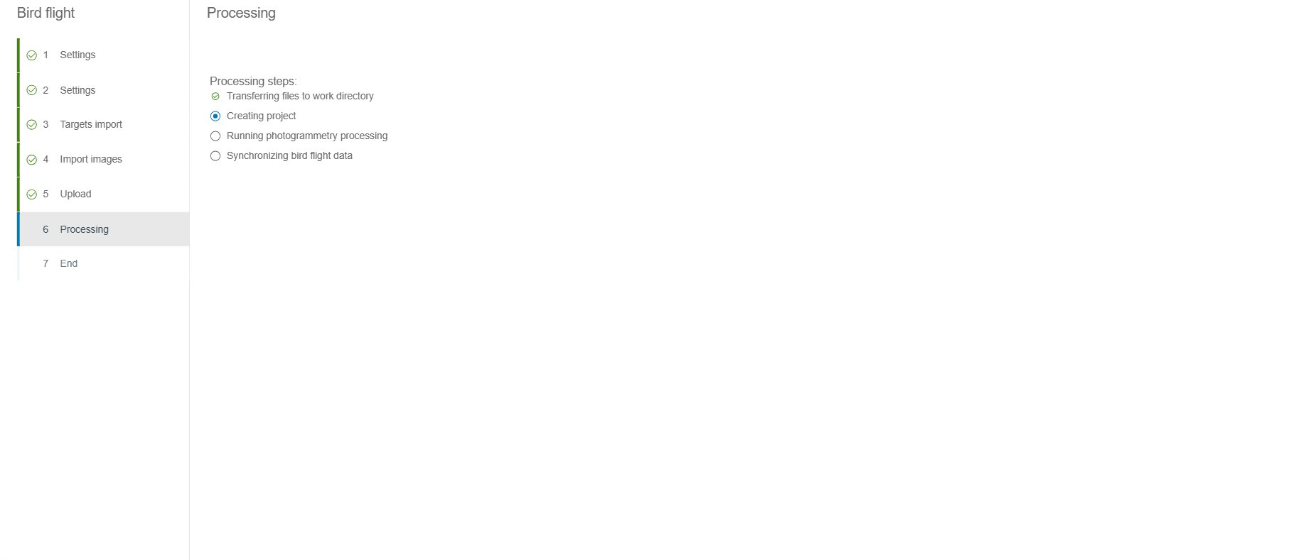
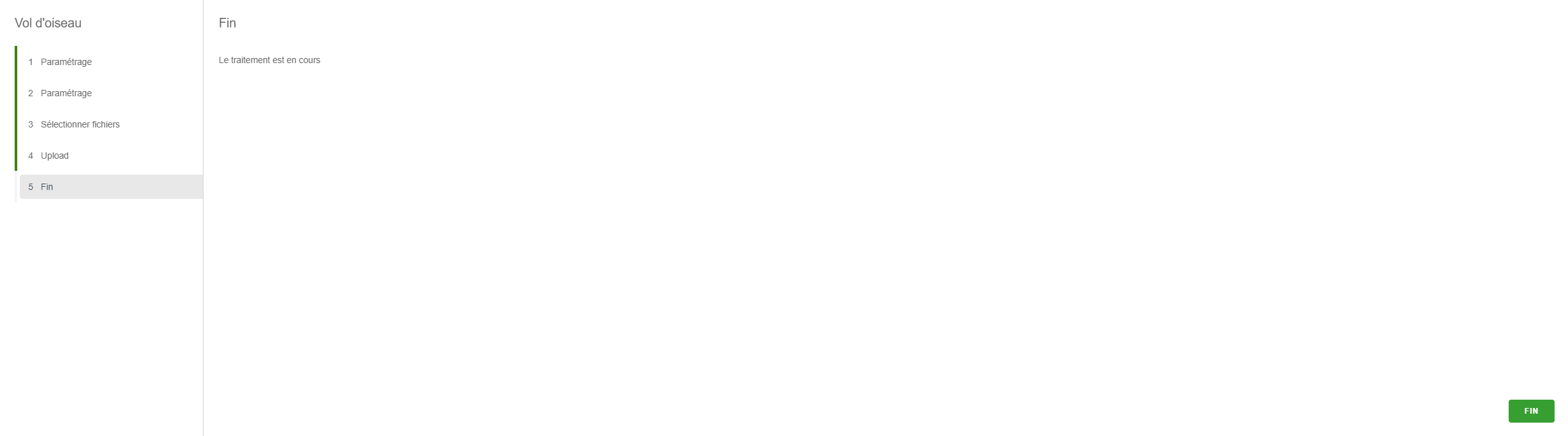
The georeferencing photogrammetric step previously ticked will be started automatically. And you can clik on "Finish" button.
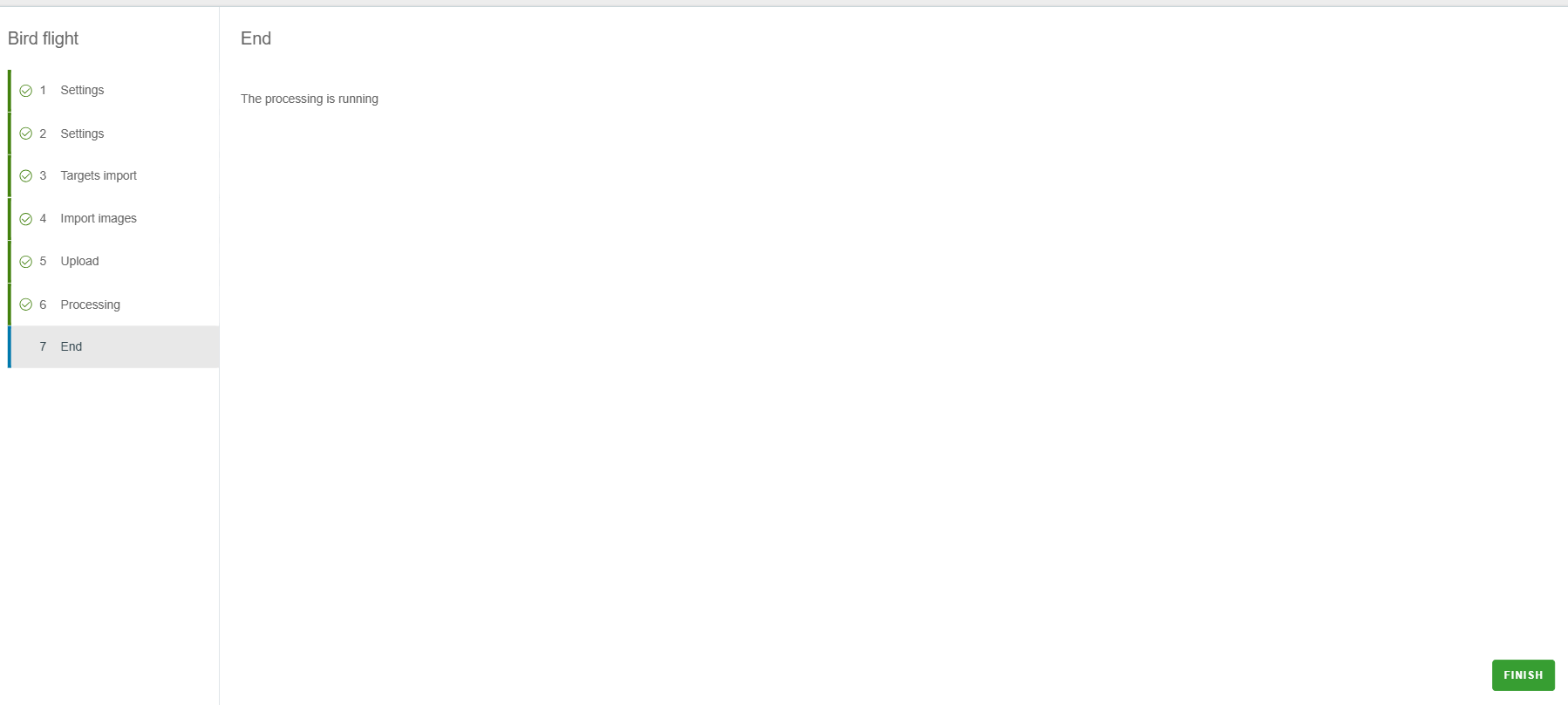
The processing of the flight is "in progress" on cloud computers. Now it's not necessary to keep our computer on this page.
¶ Control of georeferencement
¶ Control
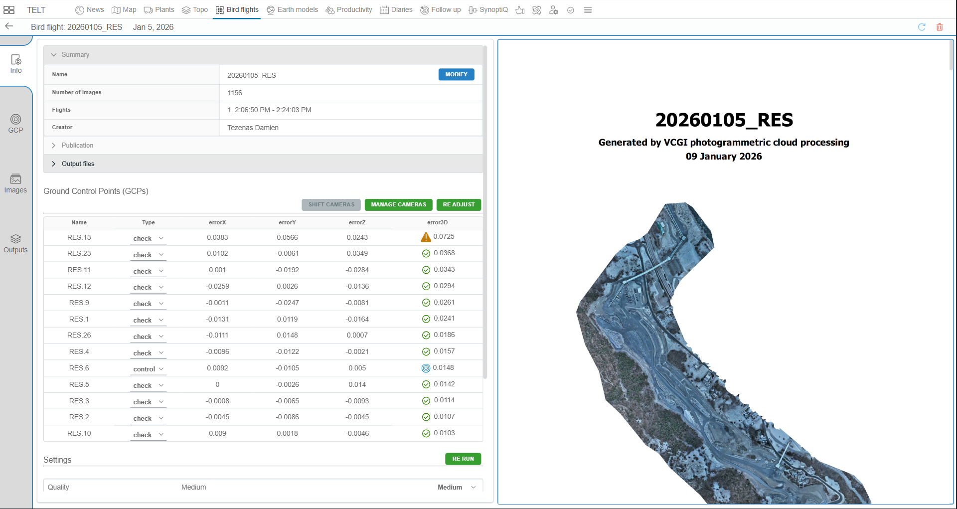
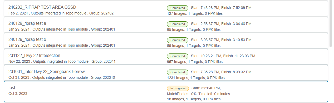
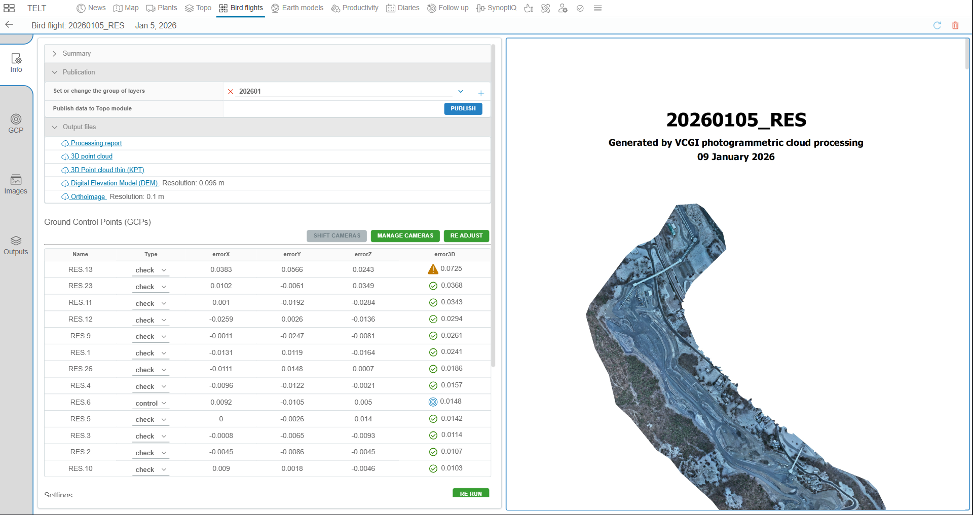
Once the first part of calculation is complete, go to the flight line name to see the report and check georeferencement accuracy.
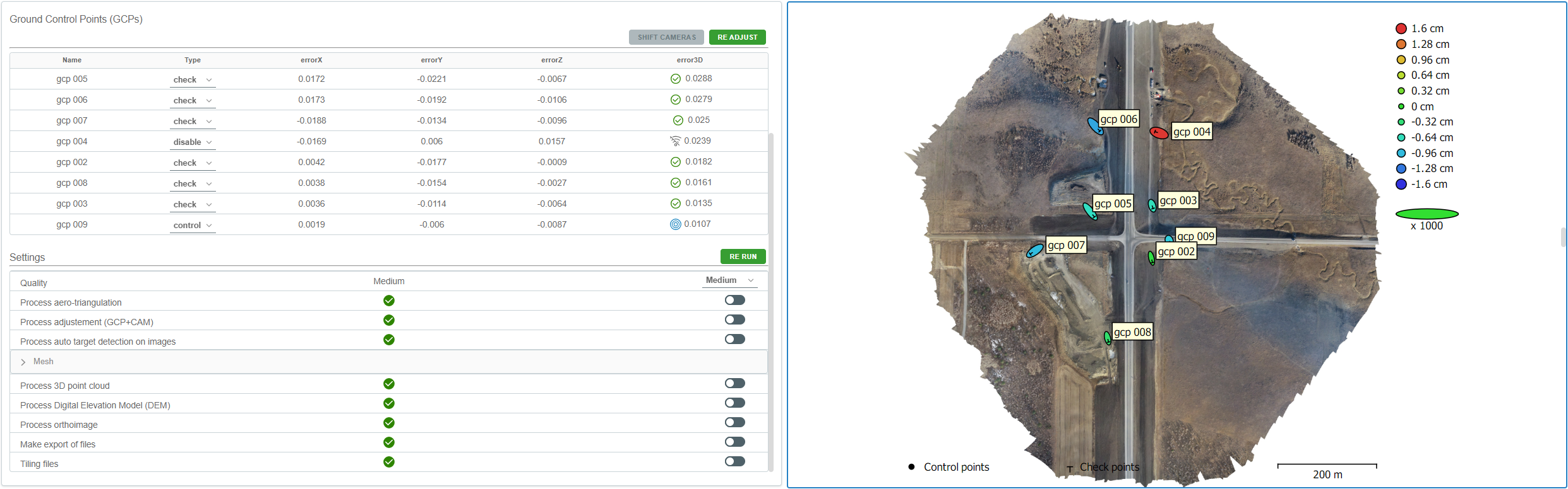
A “control” point is used with camera RTK in georeferencement.
A “check” point is not use in georeferencement and serve to control it.
A “disable” point is not use in georeferencement or check.
We have an algorithm to automatically point all GCP on images. And by default, Linaster put only one control point at the most central point of the construction site. The others point is used for checking georeferencement.
If you want to change the type of point: change the type of desired point with the drop-down list and click on “READJUST”.
¶ Shift flight
Sometimes the georeferencement have a constant shift.
For example, if the DJI base has not set up correctly (typo when inserting the coordinates).
To see it you need to put all targets in "Check" (don't forget to "READJUST"). If there is a constant shift, you see same errors in all 3 dimentions for all targets.
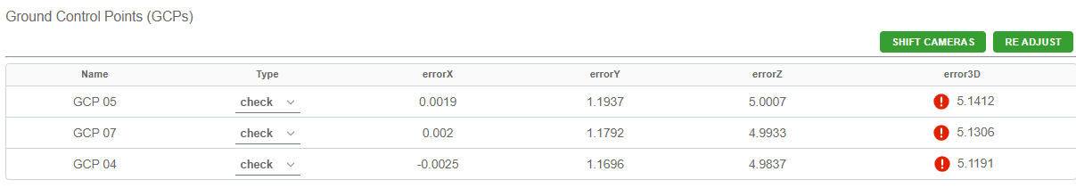
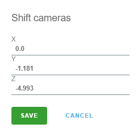
You can use the "Shift cameras" button to replace your flight in good absolute georeferencement.
A mean value of shift for each dimensions is calculated. Ajust the preset value and click on "Save".
After calculation, recontrol the georeferencement, and you can optionally set a "control" point.
¶ Creation of photogrammetric output
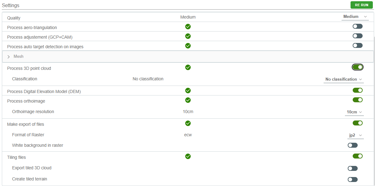
Once the georeferencing is acceptable, you can check the "Settings" boxes you want for the rest of photogrammetric processing.
-
The “Processing“ option, is the calculation of all photogrammetric outputs without exporting. In this step you can choose the GSD (Ground sampling distance = pixel size) of the orthomosaic.
-
The “Export“ option, will export all photogrammetric outputs and you can choose the format of orthoimages, and some other parameters.
-
Once all is checked, type “RE RUN” button.
Eg: The auto parameter of "orthoimage resolution" let the software use the full resolution of raw image (it can take a lot of time calculation and make heavy orthomosaïc file).
¶ Download and view the output
¶ View output
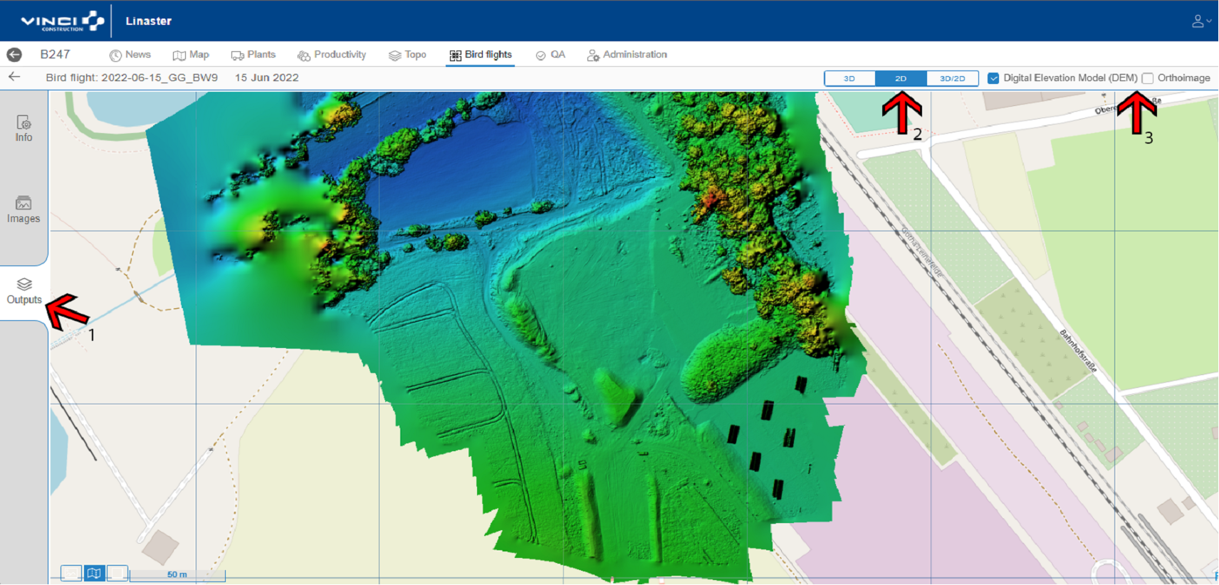
- Click on "Output" left tab (Eg. “1” in picture below), select the type of layer (Eg. “2” in picture below) and select the layer you want to view (Eg. “3” in picture below).
¶ Download output
For downloading all the output go back to the main page of flight and click on link.
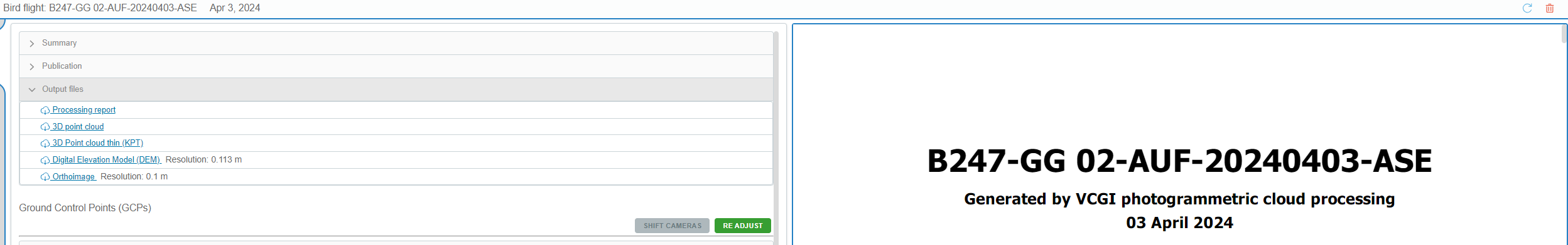
- “Processing report”: is the same report you can see on the right of this window.
- "3D Point cloud": The point cloud in “LAZ” format.
- "3D Point cloud thin (KPT)": The point cloud thinned in “LAZ” format.
This cloud is thinned by the method “model key point”. This method permits to have a light cloud and keep the resolution and shape of the full cloud. In fact the method consist of keepping one point every meter except if the altitude change of 5cm.
So, in flat area it will be one point every meter but for example in an embankment there will be a lot of point. See example below.
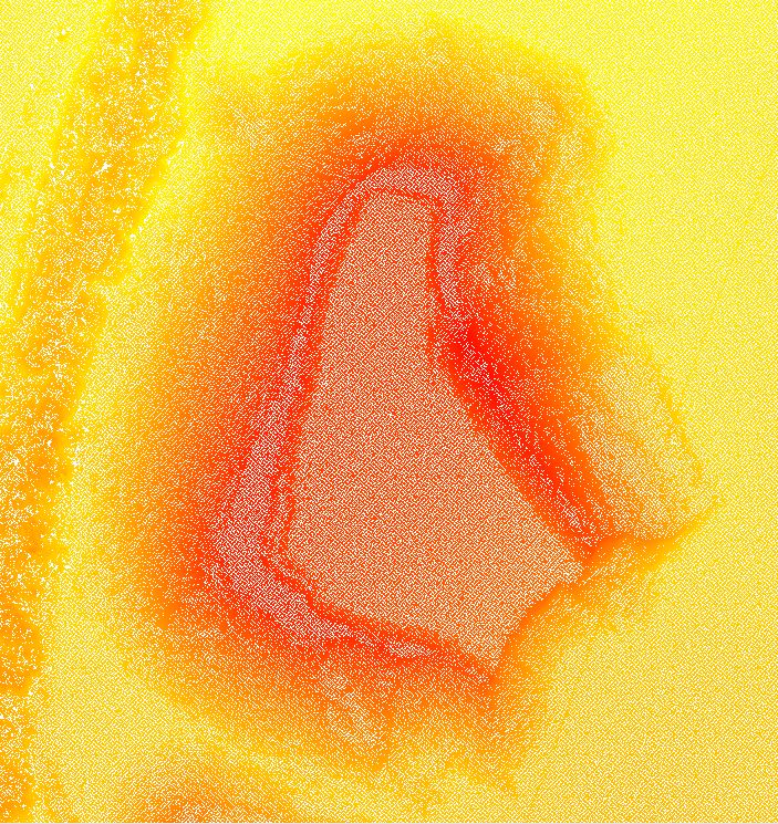
In this image, the full point cloud representing a stock |
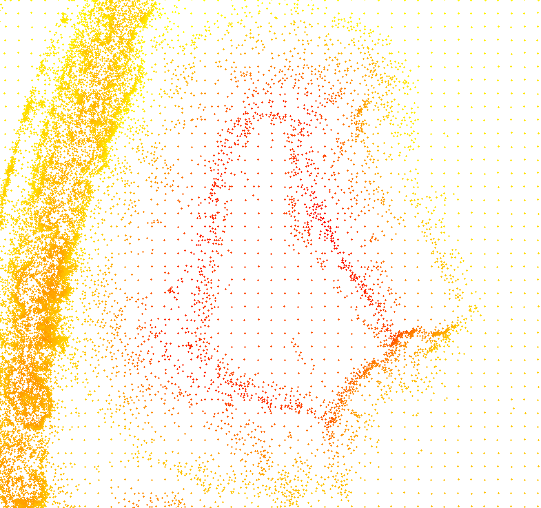
In this image, the thinned point cloud representing the same stock |
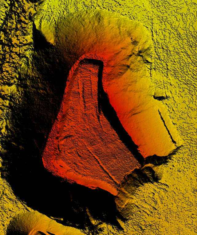
The raster DEM generated with full cloud |
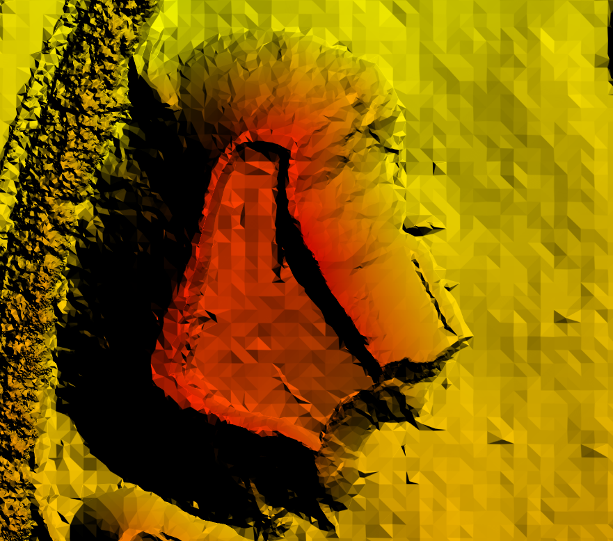
The raster DEM generated with thin cloud |
-
Digital Elevation Model (DEM): The raster respresenting for each cell the altitude.
-
Orthoimage: The Orthomosaic in previously choosed format.
¶ Publishing
Once all data is ready to be published to the Topo module, You just have to click on "Publish" button and affect a group to this birdflight (offen the month of flight)
¶ Informations about flight
In summary accordion, You can retrive some metadata of the flight. And rename the birdflight if needed.